Functions and Features
RAMScope-EXG
Multi-Measurement/Calibration Tools
for Control Algorithm Verification:
GT170 Series
Functions/Features (of the Multi-Measurement/Calibration System)
Measure the Behavior of Components in the Target Software Collectively in Real-Time, Ideal for Verification and Validation of System Functions and Performance!
Key Features
- Enables monitoring, logging, and modification (tuning) of variable data in a running control algorithm(※)
(The effects of data visualization:unforeseeable fluctuation of variables, degree of influence of instability and nonlinearity)
※The measurement load of software variables does not affect the target software.(No need to include data acquisition processing in target software) - “Combinable” multi-instrumentation system for step-by-step test requirements
Types of measurement modules: Variable Data Acquisition and Calibration,General A/D Measurement,CAN Interface
Measuring modules can be expanded to a maximum of 10 modules (including power supply and communication modules) - Multi-system in which multiple measurement modules can measure synchronously
- Equipped with a scenario function that assists test automation(Data injection into specific variables by scenario/Pseudo data transmission for CAN communication)
- An all-in-one environment that can measure and evaluate the behavior of control algorithms from reprogramming of on-chip flash MCUs
- Equipped with a calibration function that optimizes the system according to the required specifications (control parameter tuning)
- Enhanced function of measuring module (latest: compared to previous model)
Analog signal measurement (input voltage up to 1000V),CAN measurement (also follows CANFD protocol) - High-speed HOST communication IFs (GbEthernet/USB3.0), enhanced robustness and improved noise immunity
Adopted in the measurement environment for many high-voltage drive motor applications due to high withstand voltage isolation between target GND - ASAM standard (Association for Standardization of Automatic Measurement Systems) compliant: MDF (measurement data format), MCD-2 MC: A2L (variable description format)
ASAM MCD-1 XCP compliant (supports communication protocol for ECU calibration system)
Ensuring compatibility with existing ECU development experimental environment data.Enables tool linkage with other vendors' calibration tools and HILS tools
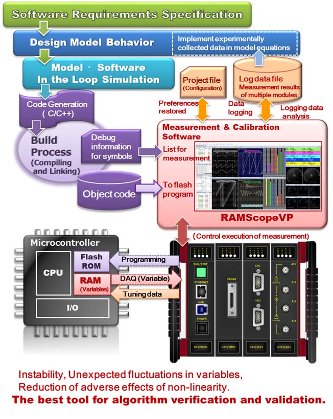
What is the Development Method for Measuring,Calibrating and Reprogramming the Behavior of Control Algorithms?
(Real-Time Target Verification Process with Our Tools(:RAMScope))
Applicable to verification processes ranging from "Unit Testing" to "System Testing" and "Product Validation"
"After Verifying the Simulation Model, Convert the Model Code into Source Code for Mass production and Generate Object Code for Target Implementation",
"Download Object Code (for On-chip Flash Memory) to Real-Time Target via RAMScope",
"Dynamic Capture of Changes in Variables of Running Control Software, and Observation of Time-series Changes like an Oscilloscope",
"Optimize Parameters to Meet System Requirements through Compliance Testing and Verification Measurements",
”Reflect Time-Series Data of Measurement Results of Realistic Control Models as Mathematical Data in Simulation Models to Improve Simulation Accuracy”
In control software development, the use of Model-Based Development (MBD) with high abstraction level is common.During the upstream design phase, we perform logical verification using simulation in combination with MBD.After logic verification of the simulation model, the control model is generated into mass production code, and the control model is verified when implemented in a real ECU environment.
In MBD development, control algorithms based on required specifications are modeled in control design. The control model uses simulation to confirm the validity of control requirements and finalize the control model for commercialization.The control model is interfaced with the platform (layers including MCAL and BSW) implemented on the control MCU to generate source code for mass production.
To convert source code into executable code for production, use a compiler to convert it to object code. After that, the elements and object code necessary for the operation of the target system are supplied to the linker/builder of the integrated development environment, and a load module file is generated to be programmed into the ROM. In verifying and testing this mass production code, the variable and parameter information required by the measurement and calibration tools uses the results generated from the integrated development environment.
The simulation analysis environment is strengthened by comparing the measurement results obtained from verification and testing of the actual target system with the simulation model, and by reflecting the obtained discrete data samples in the control model.
【Control Algorithm Verification Procedure on Target System Using RAMScope】
- Refer to the control algorithm variable information (symbol information) from the integrated development environment information and register it to the measurement channel.
(The setting environment can be saved to a project file) - Program the target object code to the on-chip flash memory MCU
- Reboot the target system after updating (on-chip flash memory MCU)
- Start of variable measurement: Data monitoring and waveform display of variable changes, Measurement data recording (save data to HOST-HDD),End of measurement operation/stop recording
- Analysis of dynamic measurement(Performance analysis using periodic sampling data、Analysis of functions and state transitions from dynamic measurement of algorithm execution)
ex: Function testing and verification(Data observation: Comparison of execution result with expected value)
Function input variable value (equivalence, boundary value) ⇒ Function output variable value - Data storage of measurement results (format: BIN/CSV/MDF), Creation of test report by copying measured data display
- Reference/edit calibration parameters、Calibration and parameter identification ⇒ Measurement of execution behavior after tuning: Re-verification
In-Vehicle Network CAN/CANFD Interface Module : Model name GT171C01
The CAN measurement module (GT171C01) is a product equipped with two channels of interfaces that have bus monitor measurement and pseudo transmission functions for in-vehicle network communication (CAN/CANFD).
Monitor measurement and pseudo sending of CAN/CANFD communication can be switched by a higher-level application according to the requirement of verification task.Signal definitions for CAN data messages can be easily configured from individual settings on the app to settings that refer to information registered in a file (.dbc) defined in Vector's CANdb.Pseudo sending can create a transmission scenario for a data pattern prepared in advance.Scenario transmission can be used as a substitute for a node in the process of development when the node is not yet completed, or for processing load tests on communication performance.At the same time, it can synchronously measure the in-vehicle network, MCU internal variables, and peripheral analog signals, making it an effective measurement tool for system verification environments.
The RAMScope-EXG measurement module can be expanded up to a maximum of 9 modules, making it ideal for measuring central gateway ECUs built with in-vehicle LANs (CAN, CANFD) that connect multiple networks.

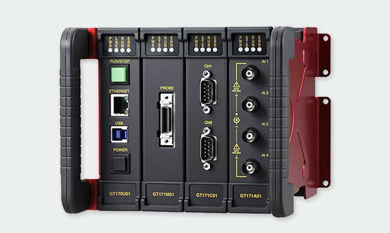
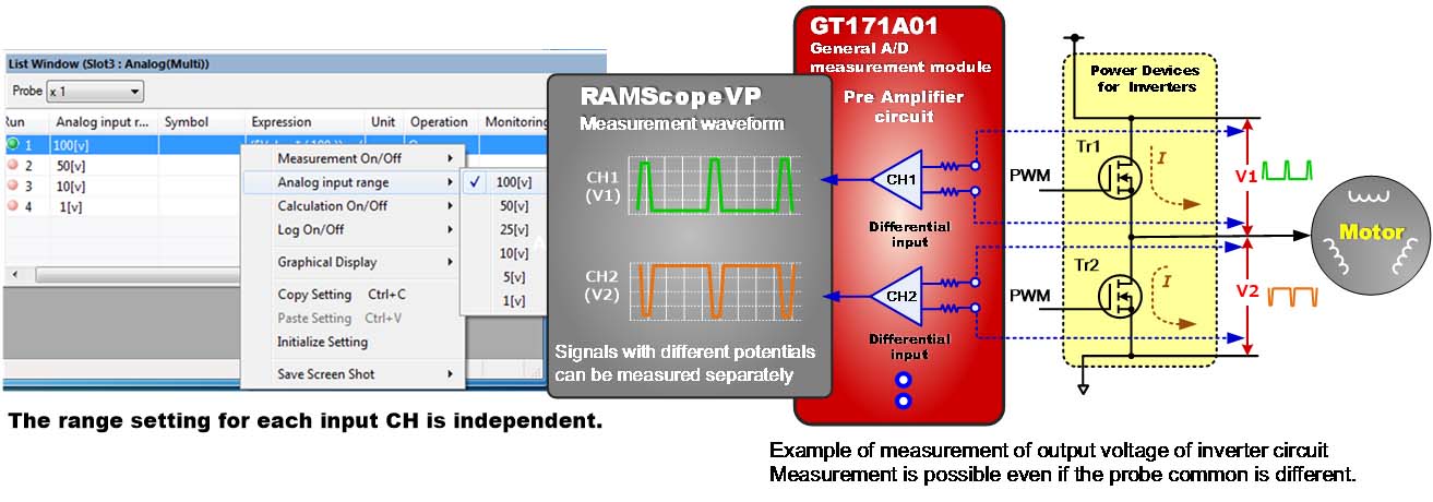
General A/D Measurement Module:Model name GT171A01
(Differential Input 4 CH - Maximum Input Voltage is 1000V (Multi-Range Compatible))
RAMScope-EXG's A/D measurement module (GT171A01) is capable of differential measurement of 4 channels of high voltage input signals (multi-range compatible) in one module.
The measurement voltage range supports a wide voltage range (multi-range) of ±1V to ±100V (CAT II) on the measurement application software.(※By using a 10:1 passive probe (maximum input voltage: 1000V CAT II), it is possible to measure up to 1000V.)
Since the measurement input uses a differential measurement method, it is easy to measure voltages with different potential differences for each channel.The differential measurement method has a high common-mode rejection ratio, making it highly resistant to disturbance noise such as noise generated in common-mode signals and crosstalk noise from other channels, enabling accurate measurements.
Synchronization of Multiple Measurement Modules
(Synchronous Measurement of Various Data and Verification of Cooperative Control of Multiple ECUs)
In recent in-vehicle control systems, autonomous distributed cooperative control systems (multi-agent systems)are attracting attention, in which independent control modules (agents) are distributed and interact with other control modules through a network.
To verify the role of distributed, independent control modules and sensors in integrated control, synchronous measurements are required to recognize the interrelationships between the behavior of each control device.The control MCU implemented in the ECU of the distributed cooperative control system performs cooperative synchronization in control tasks that link and coordinate the integrated system.RAMScope can measure multiple measurement modules synchronously, making it ideal for verifying independent distributed cooperative control.
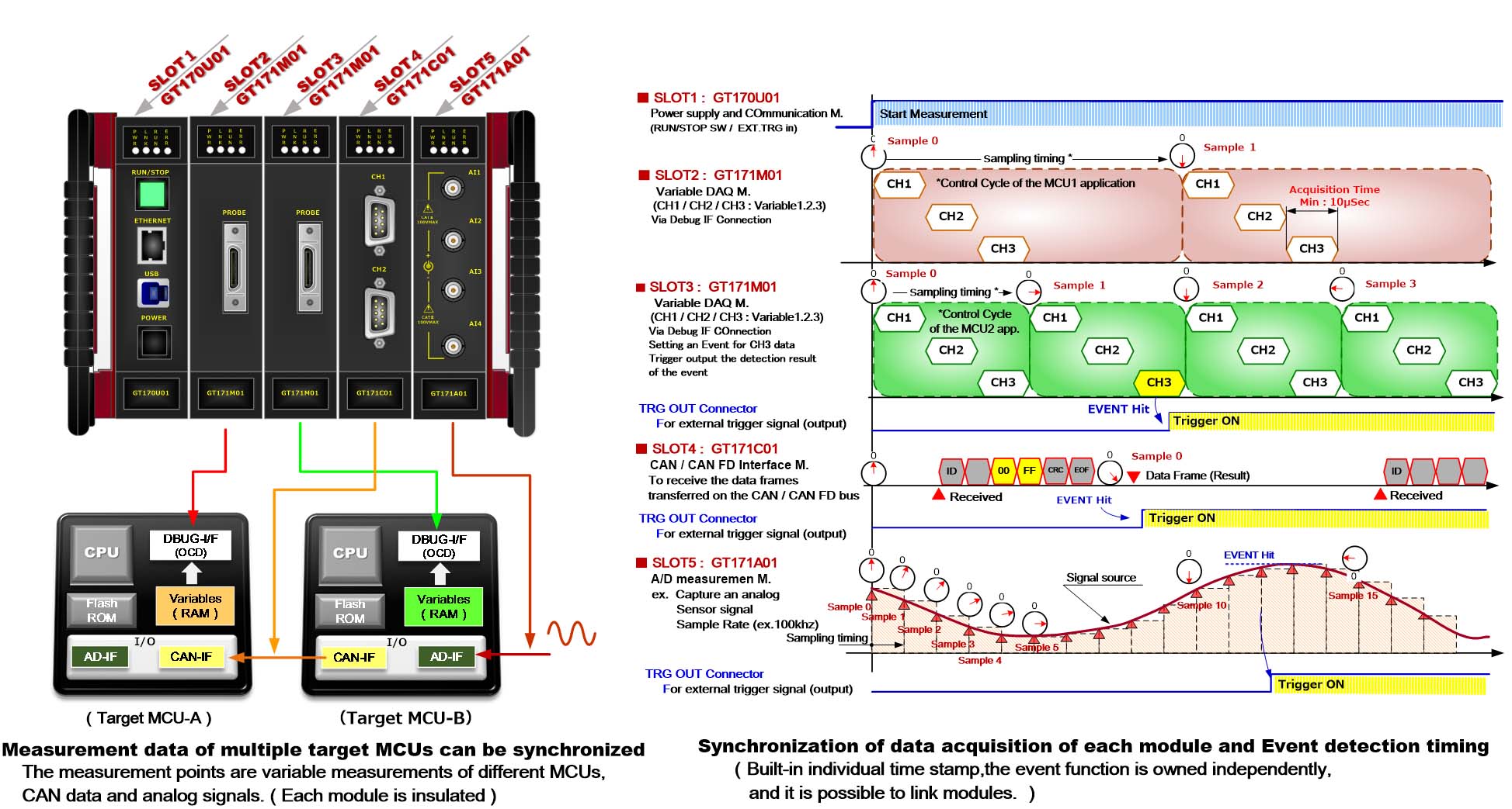
Advantages of Using RAMScope-EXG (Multi-Measurement Data Acquisition System)
- Changes in the control behavior of multiple MCUs can be observed in a time-synchronized manner
- Correlation verification by synchronous measurement of CAN/CANFD data and sensor signals in parallel/cooperative control between in-vehicle devices
- Each measurement module is equipped with an event/external trigger function that controls measurement execution
(Measurement modules other than event/trigger condition settings are also executed in conjunction (start/stop)) - The target signal and GND connected to the probe are isolated within each measurement module (High voltage:optical isolation).
Reduces the effect of common mode noise and does not affect the target system.
(High voltage isolation between measurement modules)
【Applications and Examples of Multi-Measurement Systems】
- Machine Tools with Built-in motors, Industrial Machinery, Medical Machinery, etc.
- Coordination/integration control system for multiple motion controls
- Coordinated control of multi-joint motion control (multiple motors) of multi-axis robots
- Cooperative operation of multiple ECUs through the in-vehicle network of vehicle control system
- Motor assist for HEV (Hybrid Electric Vehicle):Motor-driven to engine-driven
- Brake system for EV(Electric Vehicles):Cooperative Control of Regenerative Braking Systems for EV
- Controlling vehicle stability:Compensating control of brakes from steering(Synchronize multiple ECU measurements)
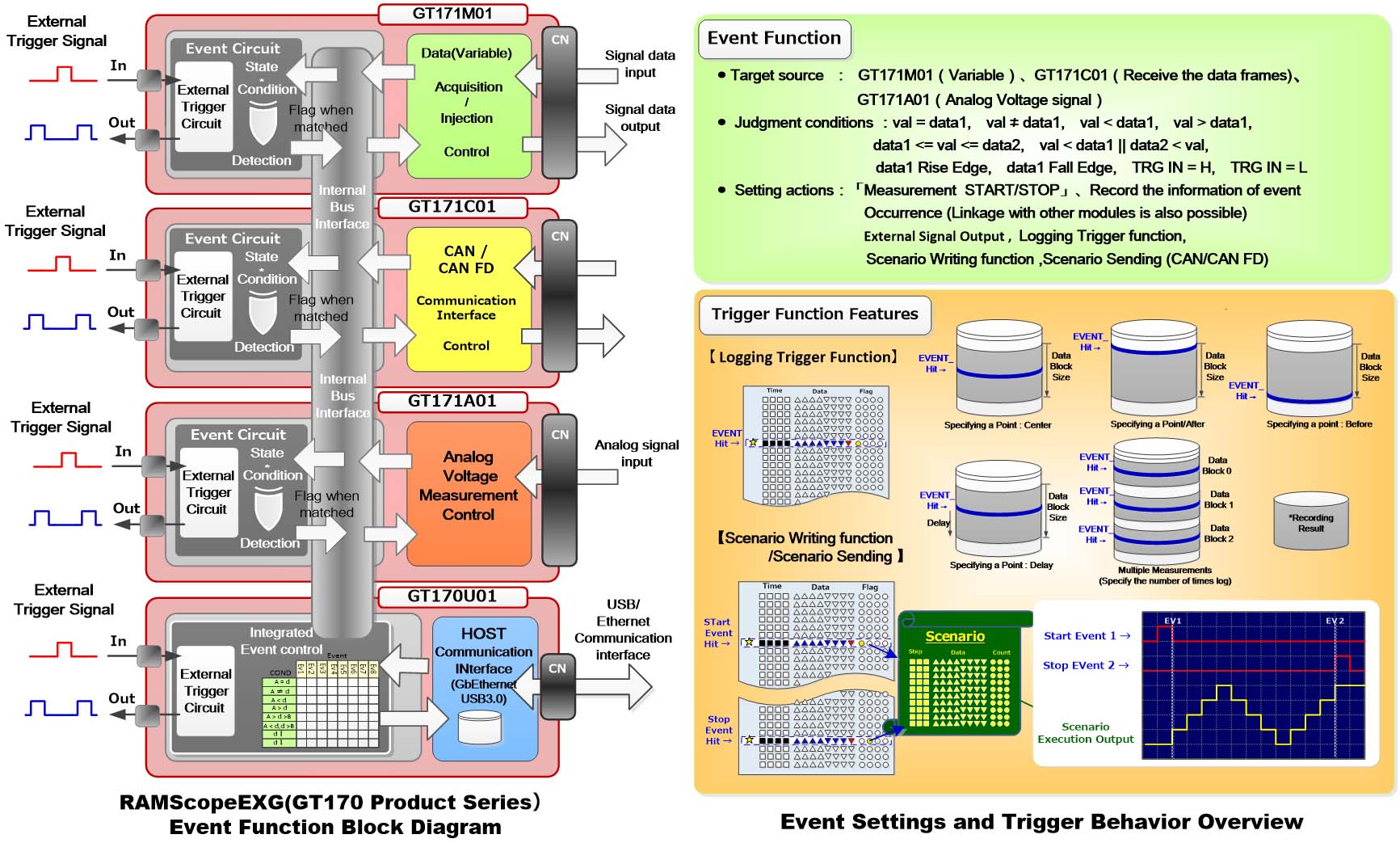
Efficient Data Capture with a Rich Selection of Event and Trigger Functions
RAMScope-EXG has an enhanced event and trigger function, improving the measurement quality for efficient failure analysis and verification tasks.The event function is an effective function for determining the characteristics and trends of the measurement target by observing notable events within the control system and the state of the control system under specific conditions.
The test operator sets conditions such as data changes of interest or sudden phenomena of interest as events in advance, and the measurement control function operates when the conditions are met during measurement.The event condition detection function can be linked to adding marks to measurement samples for identification, starting/stopping data recording, and starting/stopping scenario function operations.Each module is equipped with an event detection function to capture measurement data in real time without delay.
To link RAMScope's measurement operations with other measurement environments and target systems, each module is equipped with external trigger input/output terminals.
The external trigger input/output serves as the input for setting event conditions and the output for the results of detecting event conditions.Alternatively, it can also be used as a sampling clock input for externally synchronizing measurement data.Each measurement module functions independently.
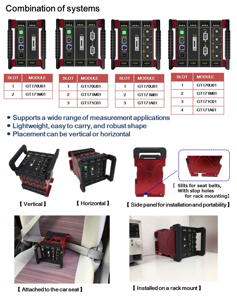
Module Combination and Flexible Installation Structure According to Measurement Scene
Measurement modules can be freely combined according to the customer's verification scene/measurement needs.Even after purchase, you can expand the combination of additional modules.
Up to 10 modules (including power supply and communication).RAMScope-EXG is a flexible system that can support various verification and evaluation environments, and has a robust structure.