Functions and Features
RAMScope-VP
Integrated Measurement & Calibration Application
for ECU Development (RAMScope only)
Functions and features(Measurement Data Visualization)
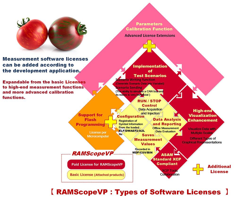
Integrated measurement and calibration applications:RAMScopeVP (Product with two grades and additional options)
RAMScopeVP is an integrated application software that is intuitive and easy to use, from connecting measurement systems and ECUs to measurement and calibration.This measurement application software can be selected from two grades to meet the verification needs of customers.
This RAMScopeVP has a free ‘standard function’ version and a paid ‘pro license’ version. The pro license version has been enhanced from the standard version.
This measurement software has "Reprogramming License" and "Advanced License" as optional products.These products allow for the reprogramming of On-chip flash memory and the expansion of calibration functions.
"Advanced License" is a paid extension product of the "Pro License" version.
Standard Functions will Adapt to Your Development
Environment (To Improve Efficiency of Measurement and Analysis)
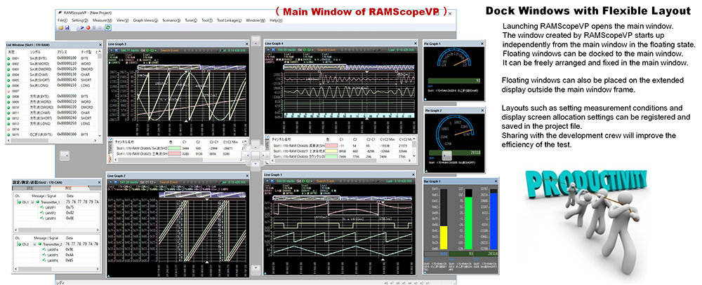
Docking window that allows measurement settings and graph displays to be freely arranged by dragging and dropping
⇒ Measured variables/signal lists, environment settings, and window layouts during test evaluation can be saved as a project file.
⇒ Uploading the same measurement environment makes it easier to redo tests and continue interrupted tests, improving efficiency.
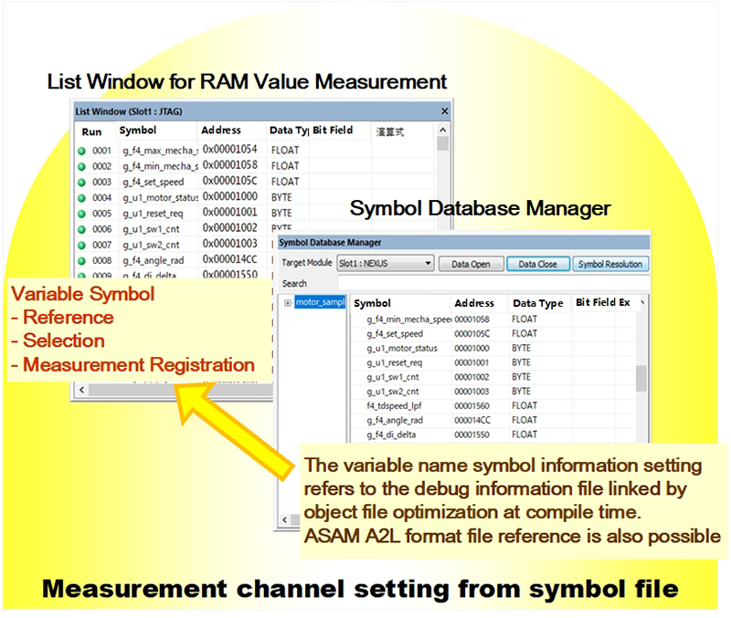
【Register to measurement channel from variable information of debug symbol file generated by compile/build】
The global variable references and registration settings of the software to be measured can be extracted from the debug symbol file generated by the latest compilation/build using the symbol data manager included with the product.
Even if symbol information registered in measurement variables is recompiled, changed information can be converted all at once.
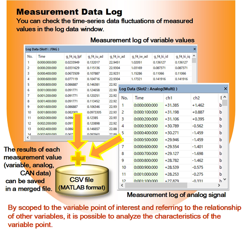
【Management of sampled measurement data for analysis】
After recording and saving measurement data acquired by the variable monitor, analog, and CAN modules to the host PC, pressing the play button will redraw the recorded data in the display window where you were observing the data (waveforms, instruments, etc.) during measurement.
Cursors in the display window can be used to observe and analyze data values, time changes, etc.The measurement data acquired by each module is output as log data in the following array image.
Depending on the requirements of the customer's analysis environment (MATLAB/FFT analysis), the recorded measurement data can be exported to CSV format files, MDF4 format files based on the ASAM standard, etc.
Further Evolving Measurement Data Visualization Applications (Paid license)
RAMScopeVP Professional license (GT020-LP/N) is updated from time to time according to customer's measurement requirements.
Calibration Assistance(Determining the Optimal Value by Parameter Tuning)
The characteristics and performance of a control system are determined by the calibration variables (calibration parameters) of the internal parameters of the control algorithm.Calibration is the task of optimizing the constant data of calibration parameters according to the requirements of the vehicle system.
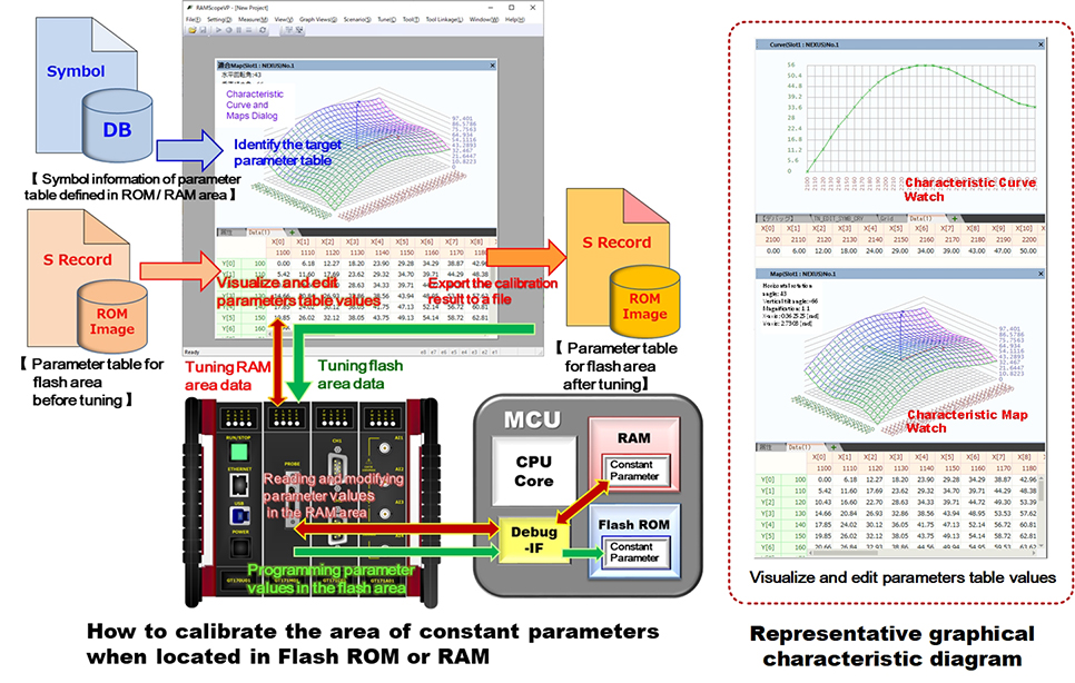
To optimize calibration parameters, RAMscopeVP provides the ability to display and edit calibration data tables and tune calibration variables (calibration function).Calibration variables can be identified by the symbol file generated after compiling and building the control software.
If the calibration parameter area is located in flash memory, RAMScopeVP can read, display, and edit the array area of the ROM data file (Motorola S format).The calibration parameters edited by RAMScopeVP can be saved as a new ROM data file (Motorola S format).To update the revised calibration parameters to the control software, reprogram the edited ROM data file to flash memory (data update).Optimization of the calibration parameters can be verified by measuring the behavior of the control system after reprogramming the flash memory.
If the parameters to be calibrated are located on RAM, you can display and edit them as calibration parameters (array/curve) by referring to the data in the memory area where the parameter table is located.Calibration is achieved by writing back the edited parameters.To confirm the validity of the parameter values in the control algorithm,the optimization of the control system is verified by measuring the behavior of the target system after parameter calibrating.
Scenario Function to Support Test Automation
(Injecting data into specific variables/Sending Simulated Data CAN Communication)
【 Scenario Function :Injecting data into specific variablesario Writing 】
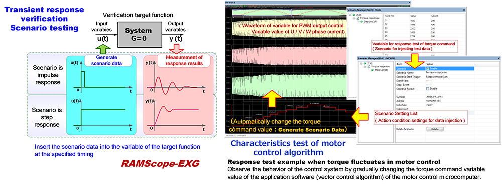
To inject data into a specific variable, a scenario is created that defines the set of time series data to be injected and the timing of the injection.This test support is a function that injects (overwrites) the specified timing and data set values registered in the scenario into the test target variables.By injecting prepared data (e.g. equivalency/boundary values) into the input data (arguments) and input variables passed to the function or module to be tested, it can be applied to functional and performance tests.
Example scenario for analyzing the dynamic characteristics of a system: Inject pseudo-step and pseudo-impulse data into the input value of a basic first-order lag function and measure the temporal change in the function's output value.
RAMScope-EXG is the perfect tool for evaluating the response characteristics of control systems.
【 Scenario Function :Sending Simulated CAN Communication Data 】
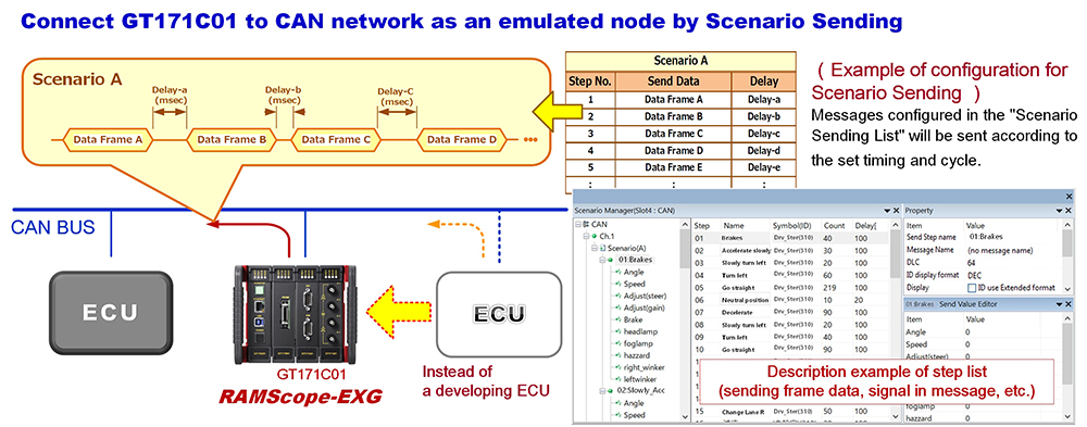
The Sending Simulated Data for CAN function defines the data pattern of CAN communication messages and the timing for sending each data in the scenario text.This function executes an operation to send simulated data to the CAN communication bus to be tested, according to a preset scenario.The operation of sending simulated CAN communication data and the measurement operation of each measurement module can be executed in parallel.The action of the scenario sending function defines a "step" as a command unit for sending one data frame.The actions defined within this step are the message to send (pseudo value), the wait time until the next sending action, and the number of times to send.When the scenario sending function is started, the actions to be sent in the linearly set steps are executed in order.
Scenario writing and CAN scenario sending operations are linked according to the start/end of measurement.It is also possible to link event conditions to scenario oTo execute the scenario function, set "Enable operation" in the settings, and the scenario function will be linked depending on the measurement operation and the fulfillment of the event condition settings.
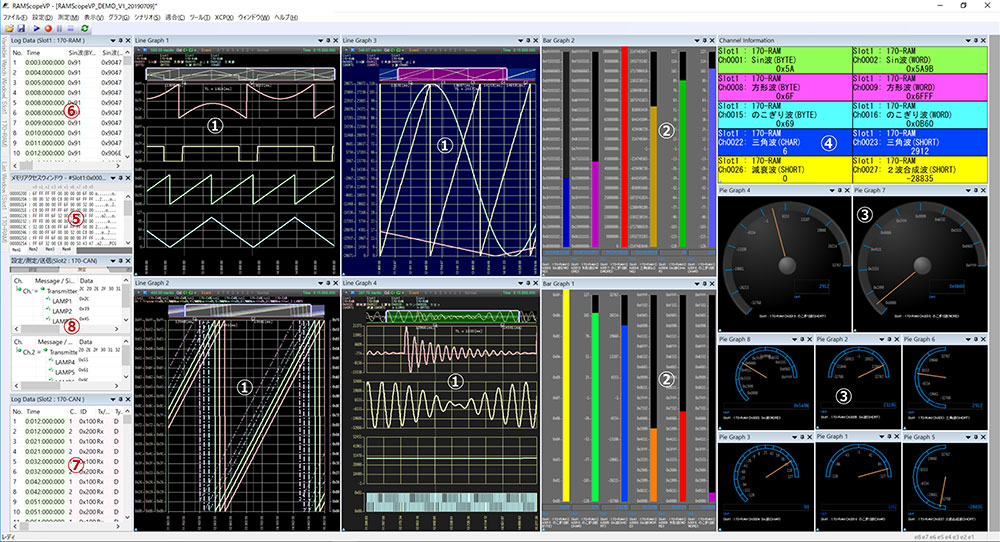
Images of Main Function Preferences (Registration/Editing) and Measurement Result Windows (Graphs/Indicators)
【 Main Function Preferences (Measurement Environment Settings)】
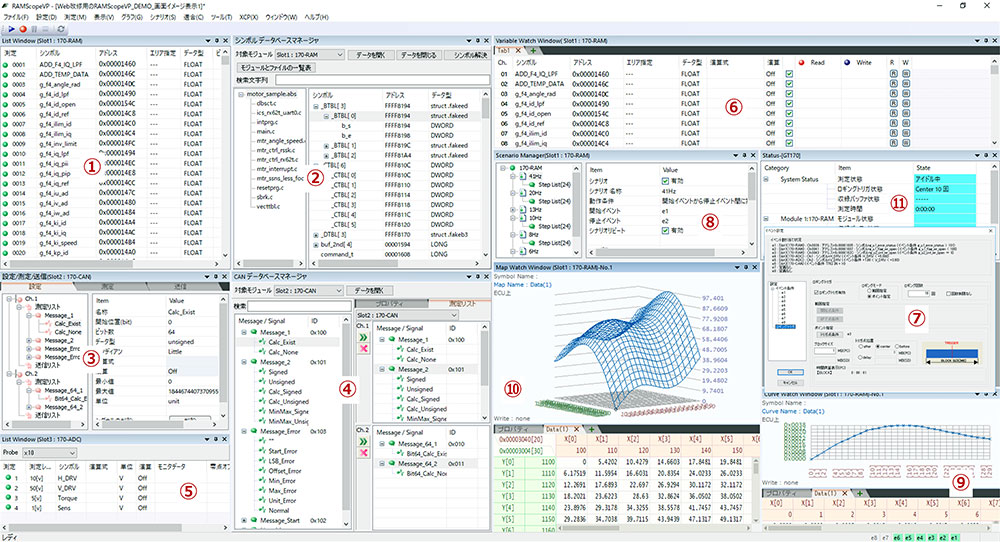
①Settings List for Variables to be Measured (ReCAN Bus Measurement Data Setting List (Message Registration/Editing)gistration/Editing) ②Symbol Database Manager: Reference variables from symbol files after build ③CAN bus measurement list (message registration and editing) ④Reference to the CAN database file(Importing CANdb (.dbc) Files)⑤Settings List for Voltage Measurement of Analog Input (Probe Magnification and Voltage Range) ⑥Variable watch window (Enables variable registration and variable monitoring and tuning) ⑦Setting Event Conditions (Controlling Start/End of Measurement)/Logging Trigger (Controlling Recording of Measurement data) ⑧List of Scenario Function Settings (Defines Data and Timing for Testing) ⑨Parameter Tuning Calibration (1-Dimensional Array: Curve Watch) ⑩Parameter Tuning Calibration (2-Dimensional Array: Map Watch) ⑪Display the Measurement System Status(Environment Settings and Execution Status)
【 Display Screen of Main Measurement Results 】
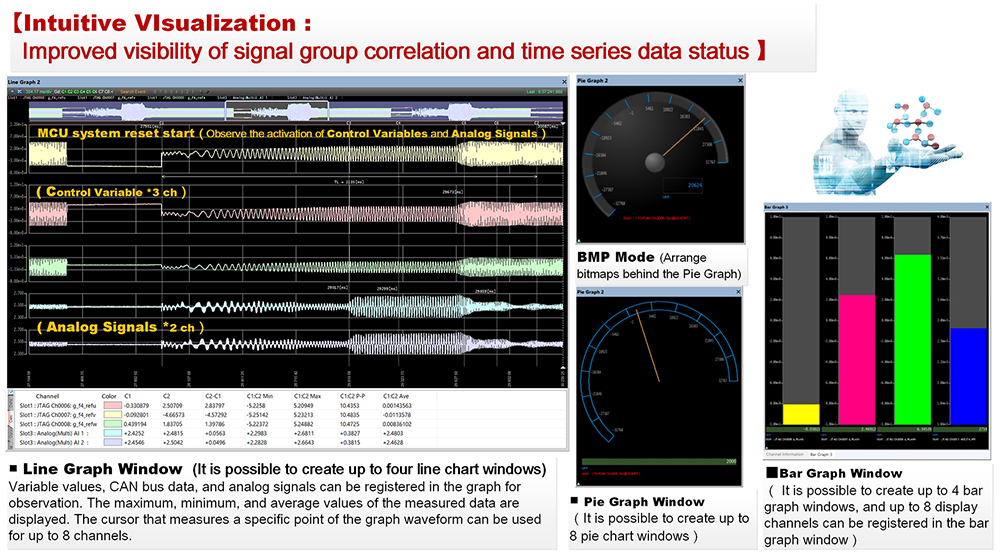
①Line Graph Window (4 Planes) ②Bar Graph Window (1 Graph (8ch up to.) × 4 Graphs Max.) ③Pie Graph (Up to. 8ch) ④Channel information (Display Columns from 1 to 8 can be selected) ⑤Memory Access Window (Dump Display) ⑥Log Data Window (Acquisition of Variable Values) ⑦Log Data Window (Acquisition of CAN Bus Data) ⑧Immediate Results of CAN Bus Data (Messages, Signal Monitor)