RAMScope:
Measurement Data Acquisition&Calibration
Product Specifications
GT170 Product Series
GT121 / GT122 Series

RAMScope-EXG (GT170 series) System Configuration
GT170 Product Series System configuration (Flexible and Scalable Data-Acquisition System)
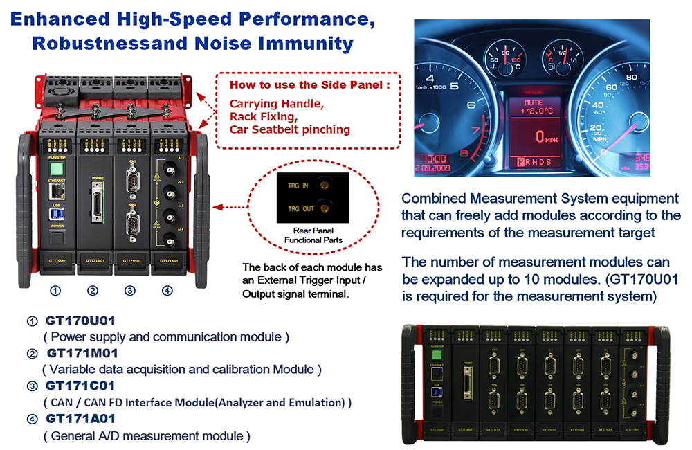
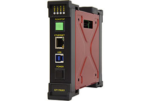
Power Supply and Communication Module : GT170U01
Number of connectable modules:Up to 9 modules
Power supply : AC adapter (DC12V) or external DC 9-16V power supply(Rating : current consumption 2.0A)
PC Interface : GbEthernet (for XCP on Ethernet connection)
USB Rev. 3.0 (for RAMScopeVP (Measurement app) connection)
Front side Switch : Power SW(Turn ON / OFF) , Measurement Start / Stop SW
Rear side CN : External Trigger IN / Trigger OUT, DC Power input(DC12V)
External dimensions : 132(H)mm×32(W)mm×157(D)mm
Accessories : Side Panels on both ends, USB-A to USB-B 3.0 Cable,
AC adopter, Power Cable, Manual CD
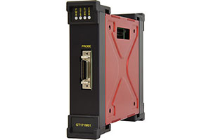
Variable Data Acquisition and Calibration Module : GT171M01
Number of registered symbol variables that can be sampled : 2048 ch (max)
Injecting data into variables (on the scenario table) : 34ch x 64 steps (rows)
Front side CN : Connector for Target MCU Connection Probe
Rear side CN : External Trigger IN / Trigger OUT
Supported Target MCU Connection Probes: GT102xx, GT103xx, GT104xx/
GT170 series dedicated probes(GT106xx,GT107xx )
External dimensions : 132(H)mm×32(W)mm×157(D)mm
Accessories:None
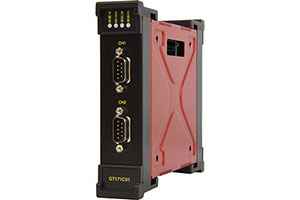
CAN Interface Module(Analyzer and Emulation) : GT171C01
Bus signal emulation function : Sending simulated CAN communication data*
(*Sends simulated CAN bus signals up to 64 steps specified in the scenario)
Front side CN : CAN, CAN FD -IF connection (D-sub 9pin) x 2 channels
Rear side CN : External Trigger IN / Trigger OUT
Supported bit rates :
CAN 2.0B : 1M, 800K, 500K, 250K, 125K (bps)
CAN FD : 8M, 5M, 4M, 2M, 1M (bps)
External dimensions : 132(H)mm×32(W)mm×157(D)mm
Accessories:None (CAN cable is not included)
General A/D Measurement Module : GT171A01
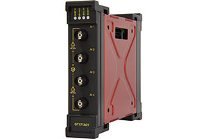
Front side CN:Analog signal input 4channels(* Differential analog input)
(* Channel-to-channel impedance within the module : 2MΩ)
Measures signals with different ground levels without the need for differential probes
Multiple analog signal voltage ranges : ±100V / ±50V / ±25V / ±10V / ±5V / ±1V
Transient Overvoltage Withstand Capability : Measurement Category 300Vrms (CAT II)
*Measurement up to ±1000V (DC + AC Peak) is possible by using a 10:1 probe
Rear side CN : External Trigger IN / Trigger OUT
External dimensions : 132(H)mm×32(W)mm×157(D)mm
Accessories:None (Analog cable is not included)
GT121/GT122 Series(for simple RAM measurement only)
**Discontinued product (**End of March 2025)
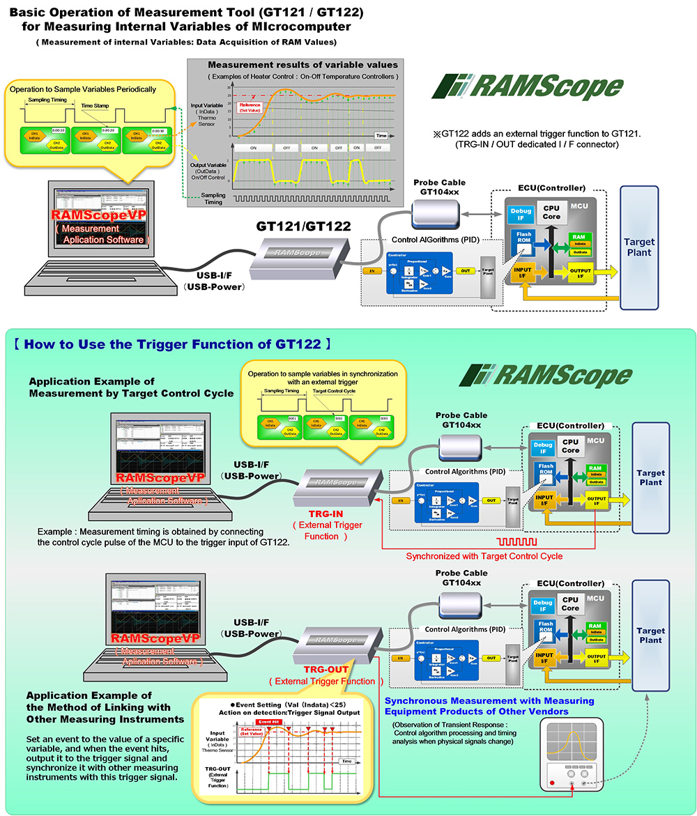
The GT121/GT122 series extracts dynamic changes in variables (internal RAM values) in real time via the microcomputer debug interface in order to measure the operation of the microcomputer control algorithm during execution.This is a dedicated variable measurement tool that enables observation of dynamic variable change data and long-term logging.
The communication I/F between the host PC and GT121/GT122 is a USB connection. Measurement operation is performed from USB power supply.
The compact measurement tool with enhanced robustness and noise resistance.The measurement probe is only for the Automotive probe GT104xx series.
RAM Monitor (measurement) Exclusively Model:GT121/GT122 Series
**Discontinued product (**End of March 2025)
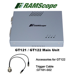
・GT121(No trigger function)
・GT122(With trigger function)
PC connecting interface:USB2.0
Power supply:Use USB power
Depends on microcomputer debug I/F specifications and measurement points
Variable (RAM) measurement specifications (reference value)
Sampling period:5 us (min) to 65 s (max) (※)
Number of measurement channels:1024 points (max)
(※)Depends on the microcontroller to be measured
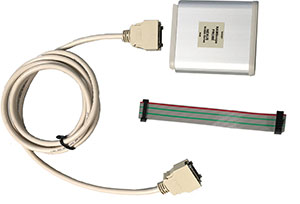
Calibration probe:GT104xx
External dimensions:(mm):126.1(W)×92(D)×21(H)mm
Trigger cable for GT122:GT181-S02(Optional accessories)
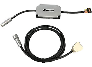
Target MCU Connection Probe for Variable Data Acquisition / Calibration
Model of the Target MCU Connection Probe : GT102xxx / GT106xxx(*)
- The probe power supply and target power supply are isolated
- Probe products differ depending on target MCU family
Configuration : Target MCU connection cable (15cm)/
Probe body - GT170M01 module connection cable (2m)
External dimensions / Weight : 82(W)mmx93(D)mmx24(H)mm / 137g
(*)For exclusive use with GT170 series (Cannot connect to GT150 series)
Automotive Grade Probe for Target MCU Connection : GT103xxx / GT104xxx / GT107xxx (*)
- The probe power supply and target power supply are isolated
- Probe products differ depending on target MCU family
Enhanced vibration resistance, Temperature range : -40 to +105 deg C
Drip-proof (waterproof) measures (Level IP44 equivalent)
(Suitable for the environment in the engine room)
Configuration : Probe body - GT170M01 module connection cable
: 5m(GT103xxx / GT107xxx ) , 2m(GT104xxx(for GT121 or GT122))
External dimensions / Weight : 63.5(W)mmx112(D)mmx20.5(H)mm / 185g
(*)For exclusive use with GT170 series (Cannot connect to GT150 series)
Product Specifications
【GT170 Product Series】
| GT171M01 | Debug interface for MCU | NBD, AUD, AUDⅡ, AUDR, RTD, NEXUS, DAP etc. |
|---|---|---|
| Sampling period | 5 us (min) to 65 s (max) ※Depends on microcomputer debug I/F specifications and measurement points | |
| Registered number of variable symbols | 2048 ch (max) | |
| Program Variables (Symbols) Watch : Memory R/W | Variable specify : 64 points×16(max), (Memory area : 256Byte(max)reference/rewriting) | |
| Timestamp | Added at the set sampling period when data is acquired(Resolution:1μsec) | |
| Display of measurement results | Byte / Word / Long size (updating real-time data in numerical value "list window"/waveform "graph window") | |
| Injecting data into variables (on the scenario table) | 30channels×64 Scenario data tables:Step execution・Repeat execution, sequential / repeat Operation condition:When Starting, Start Event, Stop Event, Reading and saving scenario files |
|
| Calibration parameters (Tuning parameters (Variables)) | Area:Internal memory of target ECU(RAM Tuning), Motorola-S format file data(Indirect ROM Tuning) Editing function:Curve Watch Window(Displaying / Editing a one-dimensional array), Map Watch Window(Displaying / Editing a Two-dimensional array) Calibration value array edit tab:16 groups registration (max), Calibration value read (ECU / File) and write (ECU / File) |
|
| External trigger | 1 input,VIN : -0.5V~+5.25V,External signal sampling measurement mode 1 output,VOUT : (select 3.3V or 5V),Scan output/Pulse output/Event output |
|
| File import File export |
Import : A2L file format(ASAM MCD-2MC Data Specification Version1.6),ELF/DWARF2 Export : MDF file format(ASAM Common MDF Version 4.1.1) |
|
| Target MCU connection probe |
GT102xxx/GT106xxx | Target side connector:14-pin (2.54 mm)pitch Pin header: 3M company connector(7614-6002xx)or equivalent Operating Environments Temperature range: -20 to +80 deg C(Specifications vary by probe shape),Humidity range:20 to 80%RH(Non condensing) |
| GT103xxx/GT104xxx/GT107xxx (Automotive grade) |
Target side connector : 14-pin (2.54 mm)pitch, Pin header : 3M company connector(7614-6002xx)or equivalent Operating Environments Temperature range : -40 to +105 deg C (Specifications vary by probe shape),Drip-proof (waterproof) measures(Level IP44 equivalent) |
|
| GT171C01 | Supported protocols | CAN Version 2.0B, CAN FD |
| Supported bit rates | CAN 2.0B:1M, 800K, 500K, 250K,125K bps, High Speed CAN (Corresponding protocol physical layer ISO1898 compliant) CAN FD:1M,2M,4M,5M,8Mbps |
|
| Number of CAN bus interfaces / Support for message addressing (Frame format) |
2 channels / 1module,Standard ID format / Extended ID format is available for each channel | |
| Timestamp | Add timestamp when message was received(Resolution : 1μsec) | |
| Display of measurement results | Message part display : Byte unit / Signal part display : Size of each set signal | |
| Bus signal emulation function (Sending Simulated CAN bus) |
Sends simulated CAN bus signals up to 64 steps specified in the scenario (Scenario step interval can be set (DELAY setting)) Select one of "Send periodically","Send sequentially." and "Send at event trigger timing(Make a scenario)" |
|
| Connector,Pin assignment | D-Sub 9pin ×2ch / CAN-H : 7, CAN-L : 2, GND : 3 | |
| Termination | 120 Ω, ON / OFF switchable | |
| File import File export |
Import:CANdb format Export: MDF file format(ASAM Common MDF Version 4.1.1), ASC file format |
|
| External trigger | 1 input,VIN : -0.5V~+5.25V,External signal level measurement mode 1 output,VOUT : (select 3.3 V or 5 V), Output when received/Pulse output/Event output |
|
| GT171A01 | Multiple analog signal voltage ranges | ±100V (resolution 5mV) / ±50 V (resolution 2mV) / ±25(resolution 1mV)/ ±10V (resolution: 0.5mV) / ±5V(resolution: 0.2mV) / ±1V (resolution 0.1mV) at the time using 10:1 probe, it’s 1000 V Measurement accuracy Within ± 0.1 %, Inter-channel impedance : About 2MΩ(common) |
| Maximum sample rate | 500KS/s | |
| Frequency range | DC~50KHz | |
| Number of input channels | 4 channels (Inter channel impedance:2MΩ) | |
| Input type | Differential analog input | |
| Timestamp | Added at set sampling period (resolution : 1μsec) | |
| File export | Expor : MDF file format (ASAM Common MDF Version 4.1.1) | |
| External trigger | 1 input,VIN : -0.5V~+5.25V,External signal sampling measurement mode 1 output,VOUT : (select 3.3 V or 5 V),Scan output/Pulse output/Event output |
|
| RAMScope -EXG (GT170 series) common |
Power supply | AC adapter (DC12V) or external DC 9-16V power supply(Rating : current consumption 2.0A) |
| Number of events and event conditions | Number of event 8 points(Up to 8 events in the entire modules), Types of event : 10 patterns (=/≠//In range/Out of range / Rise edge / Fall edge/Trigger input terminal H or L) |
|
| Event trigger of measurement system (Start / Stop of measurement) |
Up to 8 measurement data logging conditions can be set for events Logging trigger function : Data logging start / stop conditions can be set using a combination of events |
|
| System external trigger (Start / Stop of measurement) |
1 input、VIN : -0.5V~+5.25V,External signal sampling measurement mode / External signal level measurement mode 1 output、VOUT : (select 3.3 V or 5 V),Pulse output / Event output |
|
| ASAM standard compliant | MDF(ASAM Common MDF Version 4.1.1) / XCP on Ethernet | |
| Savable Log File | CSV/Binary log file(RAMScopeVP Saved as a unique binary log file) | |
| Operating Environments | Temperature range:-20 to +60 deg C (※GT171A01 : +5 to +40 deg C) Humidity range : 20 to 80 % RH(Non condensing) |
|
| About Host Computer | Computer Interface | GbEthernet(1000BASE-T) Use it when work together with third party products by XCP on Ethernet USB 3.0 |
| Recommended host computer specifications | CPU : 3.40 GHz 32 bit (x86) or 64 bit (x64) processor Installed memory(RAM): 4 GB or more, HDD : 10 GB or more of available hard disk space OS : Microsft Windows10 32bit/64bit, Windows11 64bit |
【GT121/GT122 series】
| GT121 GT122 |
Microcontroller interface | NBD, AUD, AUDⅡ, AUDR, RTD, NEXUS, DAP etc. |
|---|---|---|
| Sampling period | 5 us (min) to 65 s (max) ※Depends on microcomputer debug I/F specifications and measurement points | |
| Number of measurement channels | 1024 points(max) | |
| Symbol Watch (Memory R/W function) | Variable specify:64 points×16(max),(Memory area:256Byte(max)reference/rewriting) | |
| Logging timestamp | Added once every set measurement cycle | |
| Monitor display | Displays data in real time in Byte / Word / Long size, Numerical value "List window"・Waveform "Graph window" | |
| External Trigger(GT122) | 1 input, VIN: -0.5V~+5.25V,External signal sampling measurement mode 1 output, VOUT: (Select from 5V),Scan output/Pulse output/Event output |
|
| File Import /Export |
Import: A2L file format (ASAM MCD-2MC Data Specification Version1.6),ELF/DWARF2 Expor: MDF file format (ASAM Common MDF Version 4.1.1) |
|
| About Host Computer | Connecting interface | USB 2.0 |
| Recommended host computer specifications | CPU:3.40 GHz 32 bit (x86) or 64 bit (x64) processor Installed memory(RAM):4 GB or more, HDD:10 GB or more of available hard disk space OS:Microsft Windows10 32bit/64bit, Windows11 64bit |