BLDC Motor Control
Dynamic Visualization of Vector Control algorithms
(Capture changes in motor characteristics during the control cycle:
Sample measurement of control variable behavior at high speed and constant cycle)
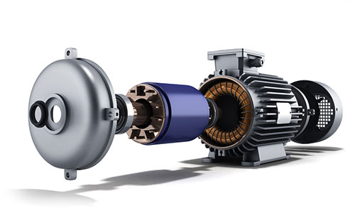
Many brushless DC motors are used in home appliances and automotive applications.To drive the motor, the control MCU performs control calculations, and depending on the results of the calculations, the PWM output (Pulse Width Modulation) of the peripheral function switches the inverter (IGBT, etc.) to control the motor's power.
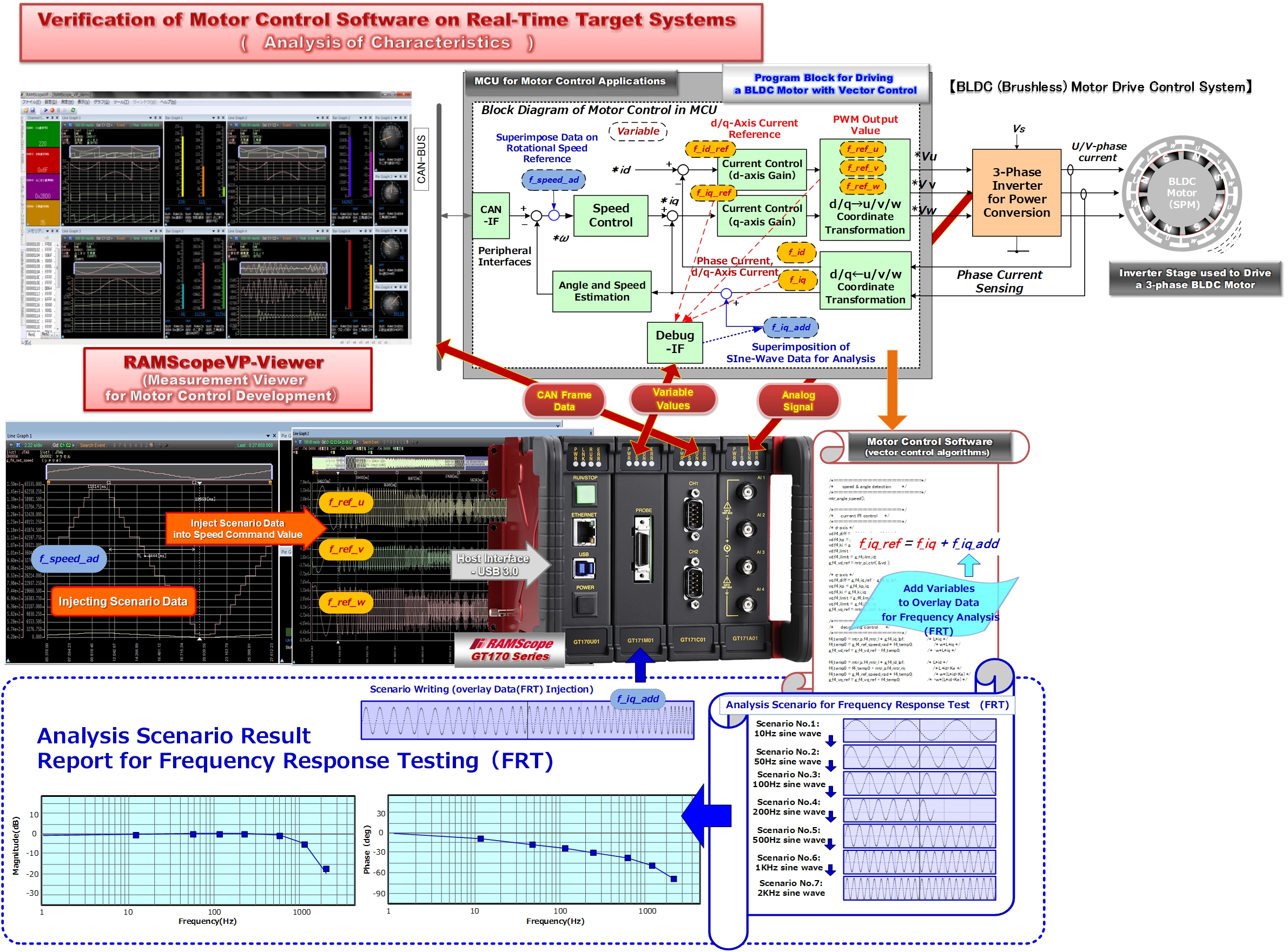
Vector control technology is the mainstream for motor control calculations.
Vector control detects the motor current (d-/q-axis) cyclically, performs calculations such as current and torque, and instantly determines the PWM output given to the three-phase inverter (U-/V-/ W-phase).With RAMScope, when the PWM carrier period is 10KHz (period 100μsec), it is possible to measure and record in real time about 10 points changes in the internal variables of vector control (d-axis, q-axis, u-phase, v-phase, w-phase, etc.).Analogue signals from peripheral inverter current and torque sensors and CAN communication of command information from external sources can also be measured simultaneously.
By applying the test support function (scenario writing), pseudo data can be injected into torque command variables and applied to endurance tests such as system response tests and repetitive change tests.
※FRTS:Frequency response verification of control response characteristics and stability can also be easily realized by applying the test support function.
(By superimposing sine wave amplitude data within the control loop, it is possible to measure changes in the feedback variable.)